This project builds a DMX controller that can control RGB LEDs for example LED stripes or LED panels. There are simply 3 DMX channels used to control 3 independent PWM output signals by using Power-MOSFETS.
The main goal for this project is to build a cheap DMX enabled light, so no special parts and only through-hole components where used.
Download the project files including the Eagle based schema and board design:
(click to open a full size picture).
In the prototype gallery you see some of the early pictures. I bought a cheap 100W Spotlight from a local dealer for less than 3 € and extracted everything from it.
The first prototype was build using a breadboard with an Serial Arduino on the back.
This is not a good design because using only 9 LEDs of red, green and blue results only in a low light but it proves that the space in such a small casing is sufficient for the electonics and the layout using MOSFETs. The power supply I used is an external 12 V socket adapter.
Because the additional components on the Arduino board that are not used I designed a new PCB board including the MosFet for driving the LEDs. With the first versions there were still some components badly placed and some connections were not correct.
The software is used is the DmxSerialRecv sample sketch that comes with the DMXSerial library.
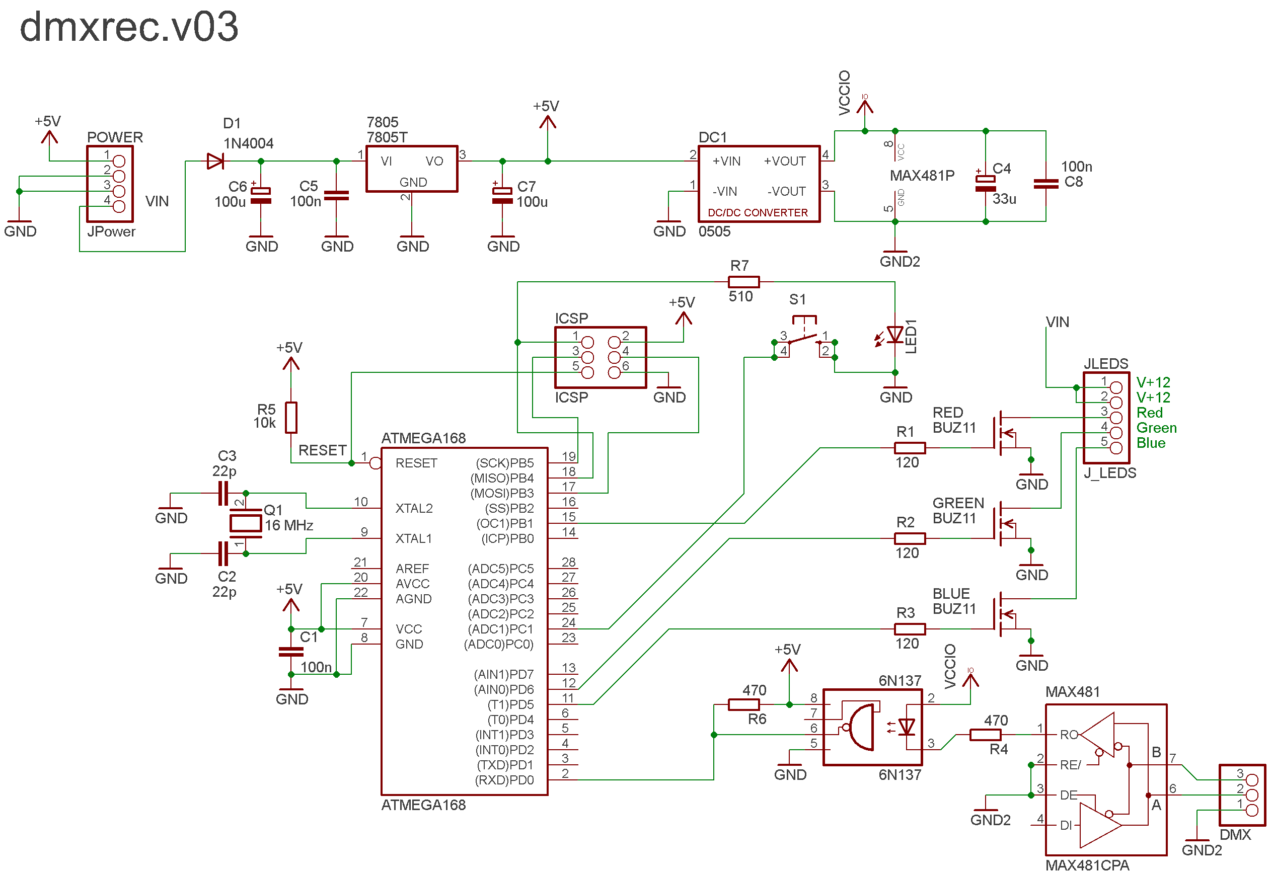
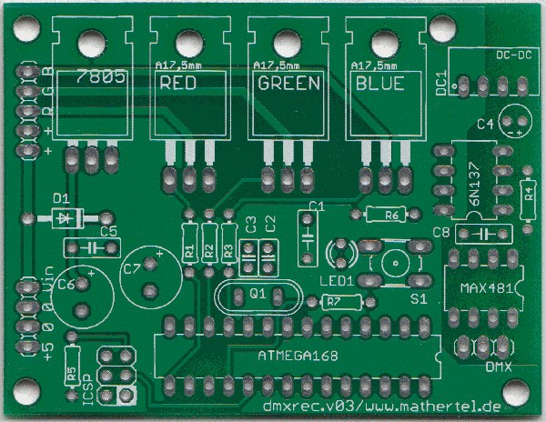
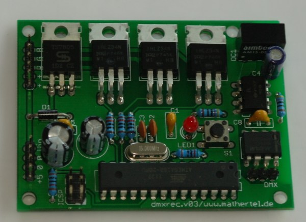
This picture shows the fist good version of the PCB for building simple LED projects with DMX control. It contains only the parts needed to receive a DMX signal including the isolation parts known from the DMXShield and 3 MosFets that can drive some amperes of load. That should be enough to control a huge amount of LEDs or some power LEDs.
The schema and the PCB eagle files are available in the download.
| Part name | Value | Description |
|---|---|---|
| R1,R2,R3 | 120 Ω | Bands: (brown, red, black, black, brown*) or (brown, red, brown, silver*) |
| R4,R6 | 470 Ω | Bands: (yellow, violet, black, black, brown*) or (yellow, violet, brown, silver*) |
| R5 | 10k Ω | Bands: (brown, black, black, red, brown*) or (brown, black, orange, silver*) |
| R7 | 510 Ω | Bands: (green, brown, black, black, brown*) or (green, brown, brown, silver*) |
| D1 | 1N4004 | A diode to protect the board against negative voltages from the power supply. |
| Q1 | 16 MHz | The 16 MHz clock crystal. |
| C2,C3 | 22 pF | The 2 capacitors for the clock crystal. ‘22’ is printed on it. |
| C6,C7 | 100 µF | An electrolytic capacitor. Be sure to place it in the right direction. |
| C4 | 33 µF | An electrolytic capacitor to filter out the noise and stabilize the voltage for
the DMX signal converter. Be sure to place it in the right direction. |
| C1,C5,C8 | 100 nF | Capacitors to filter out the noise of the power lines. Many of them are marked with ‘104’, meaning a value of 10 with 4 zeros: 100000 pF = 100 nF. |
| LED1 | A standard 3mm red led. Be sure to place it in the right direction. | |
| S1 | The switch to enter the settings for the board. | |
| 7805 | 7805 | A 5 volt regulator. Many manufacturers produce this kind of regulators. You can take any of them and ‘7805’ is printed on most of them. |
| POWER | 4 pin | The 5 pin connector the power supply. See text below. |
|
Now you can check some of the functionality of the board and check if there is
a 5 V available. |
||
| RED,GREEN,BLUE | BUZ11, IRLZ34N | The power MOSFETs. Be sure to touch a ground potential first before handling MOSFETs and don’t walk around... |
| JLEDS | 5 pin | The 5 pin connector to connect the LEDs. See text below. |
| ICSP | 2*3 pin | The 6 pin connector to program the processor. |
| ATMEGA168 | ATMEGA168 | The 28 pin chip can be soldered directly or put on a socket. Be sure to place it in the right direction. |
|
Now the processor is able to control the LED output. You can now add the bootloader
for correct settings and upload sketches. |
||
| DMX | 3 pin | The 3 pin connector to connect the DMX bus. See text below. |
| 6N137 | 6N137 | The optocoupler. The 8 pin chip can be soldered directly or put on a socket. Be sure to place it in the right direction. |
| MAX481 | MAX481CPA | A MAX481CPA from Maxim or another supplier used to convert the differential DMX
signal into a logical signal. The 8 pin chip can be soldered directly or put on a socket. Be sure to place it in the right direction. |
| DC1 | 0505 | The chip that provides another 5 v source for the DMX signal converter. |
I don't use IC sockets to make the board as robust as possible and will solder the connecting wires in the final placement.
The total cost of all the parts is around 12 € if you order them in medium quantities. Plus the PBC ist's about 20 €.
Imprint License This content is part of the http://www.mathertel.de/ web site.